After engineering thermal profiling, and after the machine is again turned on, system initialization is completed and the system is ready for operation. The main menu is displayed on the monitor screen. It lists the last board processes in (1) Board Box. In the screen's center, is (2) the component/site, and on the right is (3) the sequence/action. The GO button is very prominent, as it is located in the screen's center below (2). This screen is shown in figure 5.
The trackball/mouse (figure 6) is used to position the screen's cursor to initiate action as required. Action may be effected to select an appropriate box, as described above, make selections or changes within them or various other Windows locations and menus. After all required settings and selections are made, activating GO is the primary objective to effect rework or repair operations.
Depending upon sequences selected, other requirements as boards, components, flux, etc. may need to be specified before effecting operations. Once GO is initiated, an entire sequence is executed. It should be understood this is dependent entirely on effective operator/machine interaction.
Note: It always is possible to cancel any sequence or operation. This must be done if any discrepancy is observed that might affect safety, performance, and quality or anything else deleterious to operational effectiveness. In the operations described, only three attempts are allowed to reflow a new part.
PART IDENTIFICATION, VACUUM CONSIDERATIONS, AND NOZZLE CLEARANCE
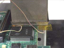
Place red arrow on part (figure 7) to make it more visible when positioning part for processing and ensure red part identification arrow or other identifying sticker is not placed over middle of part (figure 8) as pick-up tube will not make proper seal when attempting to lift it. Also ensure .200" clearance around part site before beginning any operations (figures 9 and 10)
CAUTION: REMOVE ANY CAPACITORS OR OTHER DEVICES PREVENTING ABOVE NOTED CLEARANCE SO HEATING NOZZLE AND BOTTOM BOARD SUPPORT WILL MATE FLUSH WITH BOARD SURFACES (WHEN REQUIRED TO NOT AFFECT ADJACENT PART SOLDER JOINTS) AND CAUSE NO DAMAGE TO MACHINE OR BOARDS).